ADDING MODULATION TO AN OSCILLATOR
One of the most important goals in the design of the Isle I-1 is to allow total freedom in designing modulation algortihms. Rather than stick you with a hard-coded set of algorithms with a fixed number of operators, you can build absolutely any algorithm you can dream up, with the only limit being your hardware. Any synthesis model is available, and you can mix-and-match within the same patch; you can even use the same operator as, say, an FM modulator on one carrier, and a Ring modulator on another. Any and every operator can feed back on itself, operators can be shared without limit across a Patch, and any number of operators can be defined at the system level to sync modulation across individual sounds and patches, and provide central configuration for ideas across sounds and entire compositions.
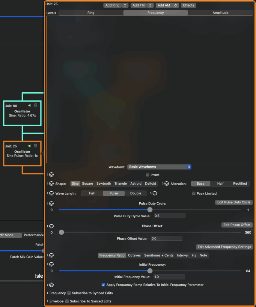
A new Patch provides you with a single carrier Oscillator, sent directly to the Mixer, set to generate a sine wave. If you create a new Patch and play a note, you will hear a sine wave at that note’s frequency. A Modulator is an oscillator which is controlling a parameter of another oscillator, which in this relationship is called a Carrier. Add a modulator to a carrier oscillator by opening the carrier’s settings panel – click on the carrier’s box in the algorithm view on the Modulation tab – and click the Add Ring, Add FM, or Add AM buttons. This will add a modulating Oscillator to the carrier. A modulation settings panel, controlling how the new modulator will affect the carrier, is added to the appropriate tab for the modulation type. You will also see the new modulator rendered in the algorithm view, above the carrier. The modulator is outlined and connected to the carrier with a color code reflecting the modulation type (aqua for Ring, orange for Frequency, and yellow for Amplitude).

There are three basic types of modulation available:
- Amplitude Modulation, of course, modulates a carrier’s amplitude – the same technique used in radio broadcasting, but at much lower frequencies (Hertz, as opposed to Megahertz). At extremely low modulator frequencies, you will hear the carrier get louder and quieter as the modulator’s wave rises and falls. At slightly higher modulator frequencies, the carrier will flutter in a manner reminiscent of mid-century sci-fi sound effects. At higher frequencies, the original pitch will be joined by additional tones, called “sidebands,” above and below.
- Ring Modulation is very closely related to Amplitude Modulation. The original tone is lost, however, and only the “sidebands” are audible.
- Frequency Modulation modulates a carrier’s frequency instead of amplitude, and again, is the same technique used in radio broadcasting, but at much lower frequencies. At low modulator frequencies where the modulator generates a sine wave, the carrier will be turned into a siren; other waveforms will modulate the carrier in ways which make their waveforms obvious. At higher frequencies, with ratios which are the same or even multiples of the carrier frequency, harmonic overtones are added, which turn a sine wave into (approximate) sawtooth or square waves, among other wave shapes. With uneven multiples of the carrier frequency, non-harmonic overtones are added, and sounds similar to metallic clangs and bells can be produced. Two kinds of FM are available – actual Frequency Modulation, which directly manipulates the carrier’s frequency parameter, and Phase Modulation, which manipulates the phase (in radians) of the carrier’s waveform, used to determine the next sample generated by the carrier. Early FM synthesizers used only Phase Modulation, but certain operations (such as feedback) involving waveforms other than sine can only be achieved using Frequency Modulation.
Watch Isle’s synthesis tutorials at https://islesynths.io/videos to get a full picture of how to use Amplitude, Ring, Frequency, and Phase Modulation, and how to apply these building blocks to make cool, interesting sounds as realistic or unrealistic as you can imagine!
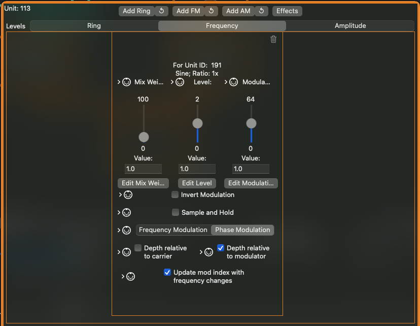
As mentioned earlier, the modulation settings panel governs how a modulator affects a carrier. You could say that this relationship is “owned” by the carrier, as a modulator could affect more than one carrier, each differently (or even the same carrier differently, with different modulation types applied). The modulation settings contain the following:
- All modulation types provide Mix Weight and Level parameters
- Level controls how much of the modulator is applied to the carrier
- Mix Weight controls the ratio of parallel modulators applied to the carrier. If you have three modulators applied to a carrier, and each has a Mix Weight of 1.0, each modulator contributes 1/3 of the modulation of the carrier – the ratio is the Mix Weight divided by the sum of each modulator’s Mix Weight. If the first modulator has a Mix Weight of 5.0, while the other two remain 1.0, then the first modulator contributes 5/7 of the overall modulation of the carrier, while the other two each contribute 1/7 of the modulation.
- Frequency Modulation contains an additional parameter, Modulation Depth. Modulation Depth contributes to the Modulation Index parameter of the FM formula described in textbooks (Level is the other contributing parameter), and is also expressed as a frequency.
- Modulation Depth can be expressed in any units in which frequencies can be expressed – as a Ratio to the frequency of the note played, as a relative number of Octaves to the note played, as a number of Semitones above or below (with fine tuning/detuning in Cents), as a Named Interval plus 0 or more octaves up or down, with the interval names provided by the tuning system, as a fixed note defined by the tuning system, or as a raw frequency value in Hertz, ranging from 0 to half the current sample rate.
- Modulation Depth in most FM synthesizers is relative to the modulator’s frequency. However, in the Isle I-1, you can also apply Modulation Depth relative to the carrier’s frequency, or as a frequency independent of the modulator OR carrier.
- The overall Modulation Index, which is derived from both Modulation Depth and Level, can optionally be updated as the oscillators change frequencies via the corresponding checkbox on the FM version of the Modulation Settings panel. Usually you would want to keep this option on, however, at the cost of a more dynamic sound, you can gain a few CPU cycles of performance by turning it off.
- The Invert Modulation checkbox will apply the inverse of the Modulator’s signal before applying it. Each Carrier modulated by the same Modulator can set this individually, so that as the Modulator’s signal rises, one carrier’s modulated parameter increases while another’s decreases.
- Normally, modulation is a smooth glide over frequency. Sample and Hold causes modulation to be broken in to steps, the duration of which is controlled by the Hold parameter. The current value of the modulator is taken, then kept and used instead of the current modulator value for the duration of Hold. When the Hold expires, the value of the modulator is taken again. This effect is best applied using a low-frequency modulator. Random (or pseudorandom) carrier values can be generated using any of the white or pink noise generators as a modulator, together with Sample and Hold.

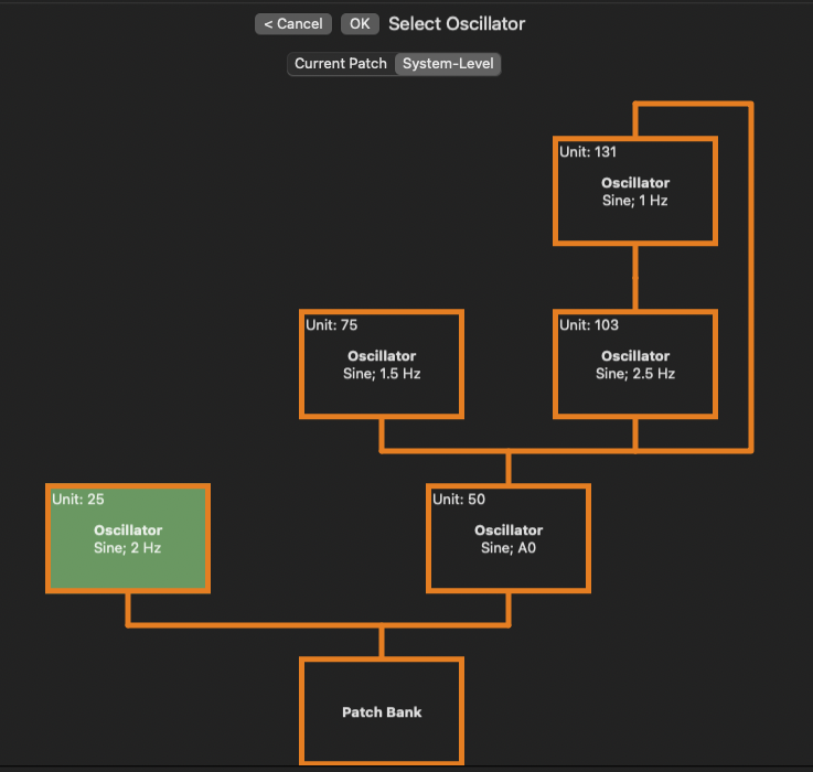
What about those looping-arrow buttons next to the Add <modulation type> buttons, you might be asking? Glad you asked – any existing oscillator in the Patch or at the system level can be added to the modulation algorithm, for any type of modulation (in fact, an oscillator which is performing one type of modulation on a carrier can also be reused to perform an additional type of modulation on the same oscillator).
- To add an existing oscillator, click the circular arrow button to the right of the corresponding “Add <mod type>” button. A dialog opens, allowing you to select any oscillator in the Patch or at the System Level, which is not already modulating the desired carrier. Ineligible oscillators will show as red and cannot be selected, while clicking on any other oscillator makes it the current selection, and highlights it in green. When you have the desired modulator selected, click OK to add the modulator to the algorithm, or Cancel to avoid adding it.
- The most common scenario for this is to add feedback, where an oscillator modulates itself, common in FM synthesis. Any oscillator can have feedback applied, and the options are not limited to a single operator feeding back – an entire modulation tree can be fed back into itself, or used to modulate other oscillators in the patch.
- After sharing the module, the algorithm diagram is updated with a new connector line from the modulator to the carrier, and a Modulation Settings panel appears in the carrier’s modulation window. All of the same settings applicable to new modulators can also be applied to shared modulators.
- Shared System-Level modulators appear in the Patch Edit view with a grey background, as they cannot be edited from the Patch Edit view. The reason for this is that System-Level objects might be used in multiple places, across multiple patches, and a change for one patch might produce an undesired behavior in another patch. Forcing updates to system-level objects to the System-Wide Oscillators panel creates a layer of separation, where more consideration can be applied before making a change (you’re welcome).
- Feedback can cut down on CPU usage, as fewer components run under the hood.
- To remove an oscillator COMPLETELY from a Patch, including all modulation relationships, click the trash can icon in the upper right corner of the oscillator in the algorithm diagram. Any oscillators which are orphaned by the removal (modulators of the modulator with no other relationships) are also removed.
- To remove ONLY the modulator relationship of an oscillator with another oscillator, click the trash can icon in the modulation settings panel in the carrier’s modulation window. If this is the ONLY relationship active for the modulator, the modulator will be removed from the Patch, along with any orphaned oscillators which modulated it.
- To remove the effects of the modulator (effectively muting the modulator to a carrier), set the Mix Level to 0.0 in the carrier’s modulation window. This might be desirable to isolate the effects of other parts of the modulation tree while developing a complex algorithm.
- Of course, a less destructive and more direct way to remove the effects of an oscillator is to simply Mute the oscillator. Each oscillator in a modulation graph has a speaker icon. When this icon is green, the oscillator is active; click the icon, it is now red and has a slash drawn through it, and it is no longer audible. Muted oscillators and their modulators continue to execute while muted, but neither their modulation effects nor their direct output to the mixer is heard. Muting can be applied in real time and via MIDI control.
Modulation can be added to any modulatable parameter value available in the Isle I-1 in a similar manner – sick of panning or flanger jet sweeps which simply go up and down or left and right? Build out a modulation tree of LFOs to add new life!


Next — Isle I-1 User Guide — Chapter 4 — Envelopes
Previous — Isle I-1 User Guide — Chapter 2 — Patches

